


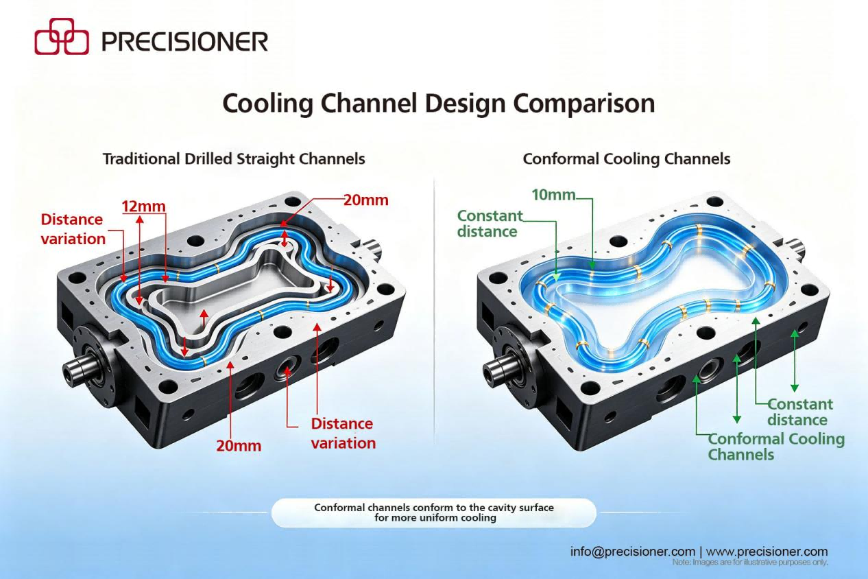
For every 1 mm increase in the distance from the cooling channel to the cavity surface, cooling efficiency drops by about 20% under typical HPDC conditions—this is a direct corollary of Fourier's law. But the real issue is that poor cooling channel design not only affects porosity but also directly determines cycle time and die life.
Body:
The rate at which cooling water removes heat is given by Fourier's law:
*q* = −*k* · ΔT / *d*
where *d* is the distance from the channel center to the cavity surface. When *d* increases from 10 mm to 12 mm (+20%), the heat flux *q* decreases by about 17%; when it increases to 15 mm (+50%), *q* decreases by 33%.
Optimum spacing
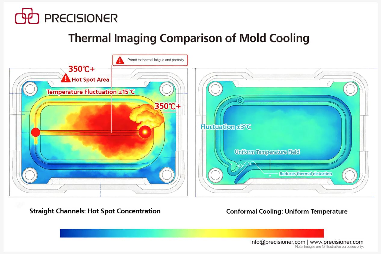
at *s*/D = 2, the temperature fluctuation is approximately ±8 °C; at *s*/D = 4,
the fluctuation is about ±20 °C. Excessive temperature fluctuations exacerbate thermal fatigue and shorten die life.
Quantitative benefits of conformal cooling
In the case study below, conformal cooling delivered:
- reducing cooling time by 15–25%;
- lowering hot spot temperatures by 30–40 °C;
- significantly reducing shrinkage tendency.
Design procedure
1. Identify hot spot regions (temperature > 350 °C) using thermal imaging or mold flow analysis.
2. Calculate the required cooling capacity: Q = ρ · V · cₚ · ΔT/t_cycle.
3. Determine the channel diameter: D = 4Q / (π · v · ρ_water · cₚ,water · ΔT_water).
4. The minimum turning radius for conformal cooling channels should be ≥ 3D to avoid flow separation.
5. Implementation: 3D printing or split inserts with seals.
Case data
In a motor housing die-casting mold, the original straight-line channels had
*d* = 12–20 mm, a cycle time of 98 seconds, and a porosity rate of 5.2% at the hot spot. After adopting conformal cooling channels (*d* = 10 mm constant), the cycle time dropped to 74 seconds, porosity fell to 0.7%, and die life increased from 70,000 shots to 180,000 shots.
Author: Precisioner metal Engineering Team.
Contact our engineering team to discuss how conformal cooling can optimize your specific application.
info@precisioner.com