


By Precisioner Engineering Team
Many high-pressure die casting (HPDC) plants face a common challenge: a new die passes all CMM (coordinate measuring machine) inspections after finish machining, but after roughly 30,000 shots in some projects, issues such as increased flash, leakage at the parting line, continuous drift of critical dimensions, and out-of-tolerance batch variations gradually appear. Most people attribute this to heat treatment deformation, bench fitting, or mass production parameters. However, we traced back to root causes through our project reviews. many hidden risks are introduced during the rough machining allowance allocation and tool selection stages.
The dimensional stability and service life of die-casting dies are not determined by finish machining alone; they are strongly influenced by the rough machining process. The uniformity of the rough machining allowance, datum consistency, and tool adaptability directly affect the correction space for subsequent heat treatment deformation, the datum accuracy for finish machining, and the appropriate electrical discharge machining (EDM) stock allowance.
Key takeaways:
· Roughing is not just stock removal; it sets the datum chain, stress state, and correction space for every later process.
· Tool material, coating, and cutter geometry should be matched to steel condition and cavity geometry.
· Datum discipline and graded allowances reduce mid-production drift, rework, and sealing-surface risk.
· Precisioner standardizes these variables in an internal rough-machining parameter table.
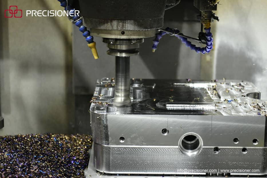
Figure 1: Rough machining of a Precisioner HPDC die — a solid carbide end mill removing large stock allowance in the cavity. Chip morphology and tool marks indicate cutting load and allowance stability.
Body
I. Tool Material and Coating: Controlling Allowance Stability and Reducing Progressive Dimensional Deviation
For rough machining of die-casting die steels such as H13 and SKD61 in the annealed or pre-hardened condition, high-speed steel (HSS) tools are not recommended for cavity roughing. Solid carbide end mills are recommended for cavity roughing and corner cleaning; indexable carbide tools can be used for large-volume face milling depending on machine rigidity and cavity geometry. Coating selection should match the working conditions to reduce the risk of uncontrolled allowance variation caused by rapid tool wear.
For conventional rough machining, TiAlN coating is preferred due to its good high-temperature resistance and wear resistance. It is suitable for large stock removal in die-casting die steels within typical hardness ranges, with a stable wear rate that helps prevent sudden allowance spikes over a short period. For high-speed cutting and high-load deep-cavity machining, AlTiN coating, which has higher oxidation resistance at elevated temperatures, can help suppress thermal wear and edge chipping and, with tool-life monitoring, maintain consistent roughing allowances across the die plate.
If coating and material selection do not match, the tool may experience rapid wear and edge chipping, which can directly cause roughing allowance variations. Subsequent finish machining may require additional toolpaths and tool regrinding, which can compromise datum consistency and accumulate machining stresses, creating hidden risks for later mass-production deformation.
II. Precise Matching of Tool Shape and Allowance: Bull-nose Cutters Instead of Ball-nose Cutters to Reduce Deformation and Overcut Risks
For open cavities and large surface areas in die-casting dies, ball-nose cutters are sometimes used for roughing, but they are often inefficient. In Precisioner's standardized process, bull-nose cutters (corner-radius end mills) with layered cutting are preferred for open and medium-to-small cavities, with the corner radius controlled at 0.8–2.0 mm. For large cavities, a larger corner radius may be selected according to cavity depth, steel hardness, and tool rigidity. Allowances are matched to cavity depth and steel hardness.
Bull-nose layered cutting provides more uniform cutting loads and lower cutting resistance, reducing the need for excessive clamping force. This helps minimize clamping deformation and machining displacement in deep-cavity dies and thin-rib structures, and reduces the heavy-load, vibration, and overcutting risks often associated with ball-nose roughing. Final vibration and overcut risks still depend on machine condition, tool overhang, fixturing, and toolpath strategy.
After bulk material removal across the plate, a step-down corner clearing process is applied: Solid carbide tools one size smaller in diameter than the previous tool are used for layered corner clearing. By progressively reducing tool diameters, residual stock in cavity corners and rib features is removed more precisely, helping ensure a more uniform allowance across the die before semi-finish machining.
III. Tool Path and Datum Chain Control: A Unified Datum Chain in Rough Machining to Reduce Cumulative Errors
Many precision errors in die machining stem from inconsistent datums. For die bases, cavities, cores, inserts, and sliders, datum corners and datum planes should be defined and unified before rough machining begins. A unified datum chain should be maintained, and any datum transfer after heat treatment or re-fixturing must be controlled and verified.
When machine travel and cutter diameter permit, datum surfaces can be machined with large-diameter face mills in a single pass. This reduces tool marks and height differences caused by multiple step-overs and helps ensure the flatness and perpendicularity of the datum surfaces, in combination with machine geometric accuracy and proper fixturing. It provides a more stable datum for subsequent finish machining, EDM, and assembly positioning.
We also optimize the structural machining strategy. At the transition between the moving half's protruding features and the parting line, an R3–R5 mm circular arc transition band may be reserved where the design permits and the area is not a sealing or fitting surface, to avoid residual stress from sharp corners during rough machining. This helps reduce the risk of stress concentration and micro-cracks after heat treatment and improves die service life from a process perspective.
IV. Differentiated Allowance Standards by Structure
Instead of a one-size-fits-all allowance practice, rough machining allowances are set in grades based on stress, sealing, and fitting conditions, balancing machining efficiency with later correction space:
· Conventional cavity surfaces: roughing stock of 0.3–0.5 mm per side, to be removed during semi-finish/finish machining and polishing.
· Weak structures such as deep cavities, thin ribs, and high steep surfaces: roughing stock of 0.8–1.5 mm per side, to help offset heat treatment deformation and machining stresses. The final value should be validated according to part size, wall thickness, and heat treatment conditions.
· Parting lines, sealing surfaces, and slider fitting surfaces: roughing leaves a controlled base stock; semi-finish equalizes the stock; final accuracy is achieved by finish machining, grinding, or bench fitting. This helps avoid repeated rework of the sealing area.
Precisioner has established an internal standardized "Die Casting Die Rough Machining Tool Selection Parameter Table" covering die steels such as H13 and SKD61. It specifies tool material, coating, corner radius, cutting speed, feed parameters, and allowance allocation standards for different structures, supporting standardized implementation and reducing errors caused by reliance on individual experience. The table is available upon request under a non-disclosure agreement (NDA).
Let’s Compare Notes
To our fellow die engineers: is your CNC rough machining allowance differentiated by structure? Have your tool selection and cutting parameters been developed into a standardized system rather than relying on experience? Feel free to share your process pain points in the comments.
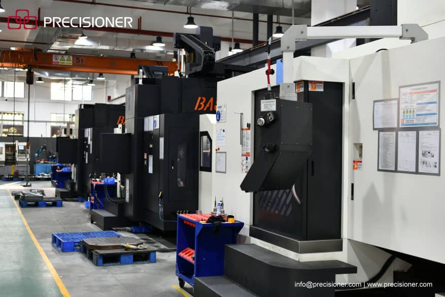
Figure 2: Some of Precisioner's CNC rough machining equipment — large-travel machines and stable spindle rigidity are the foundation for single-pass machining of datum surfaces and uniform allowance control in large dies.
Work with Precisioner
If you are developing a large HPDC die and are currently in the design or rough machining stage, send us your drawing package for a complimentary rough machining process review.What you receive:
· Rough machining allowance allocation review by structure
· Tool material, coating, and corner-radius recommendations
· Datum chain and toolpath strategy check
· A practical risk list for deformation, sealing surfaces, and rework
· A 30-minute technical review call with our engineering team
What to send:
· 2D and 3D die drawings or cavity and core models
· Die steel and hardness condition
· Cavity size, tonnage, and project stage
· Current roughing parameters, if available
Drawings are handled under strict confidentiality. We can sign an NDA before receiving your files.
Contact: info@precisioner.com
Subject line: HPDC Rough Machining Review – your company name
Have a specific rough-machining challenge? Our engineering team is glad to review it with you—no obligation.