



By the Precisioner Engineering Team
The die base is the skeleton of an HPDC die and the datum for every dimension in it. A cavity insert machined to tight tolerance will still flash, stick and drift if it sits on a plate that deflects, and the problem usually surfaces months into production, when reworking the insert alone can no longer recover it.
Let the boundary be drawn first. The die base does not determine the thermal fatigue life of the insert material, and it does not replace the contribution of the insert and the casting process to first-part quality. What it determines is plate stiffness against deflection, guiding reliability, fit stability at operating temperature, and interface compatibility with the press. In other words, it determines the accuracy retention of the die base itself, and through that the long-term production stability of the whole die.
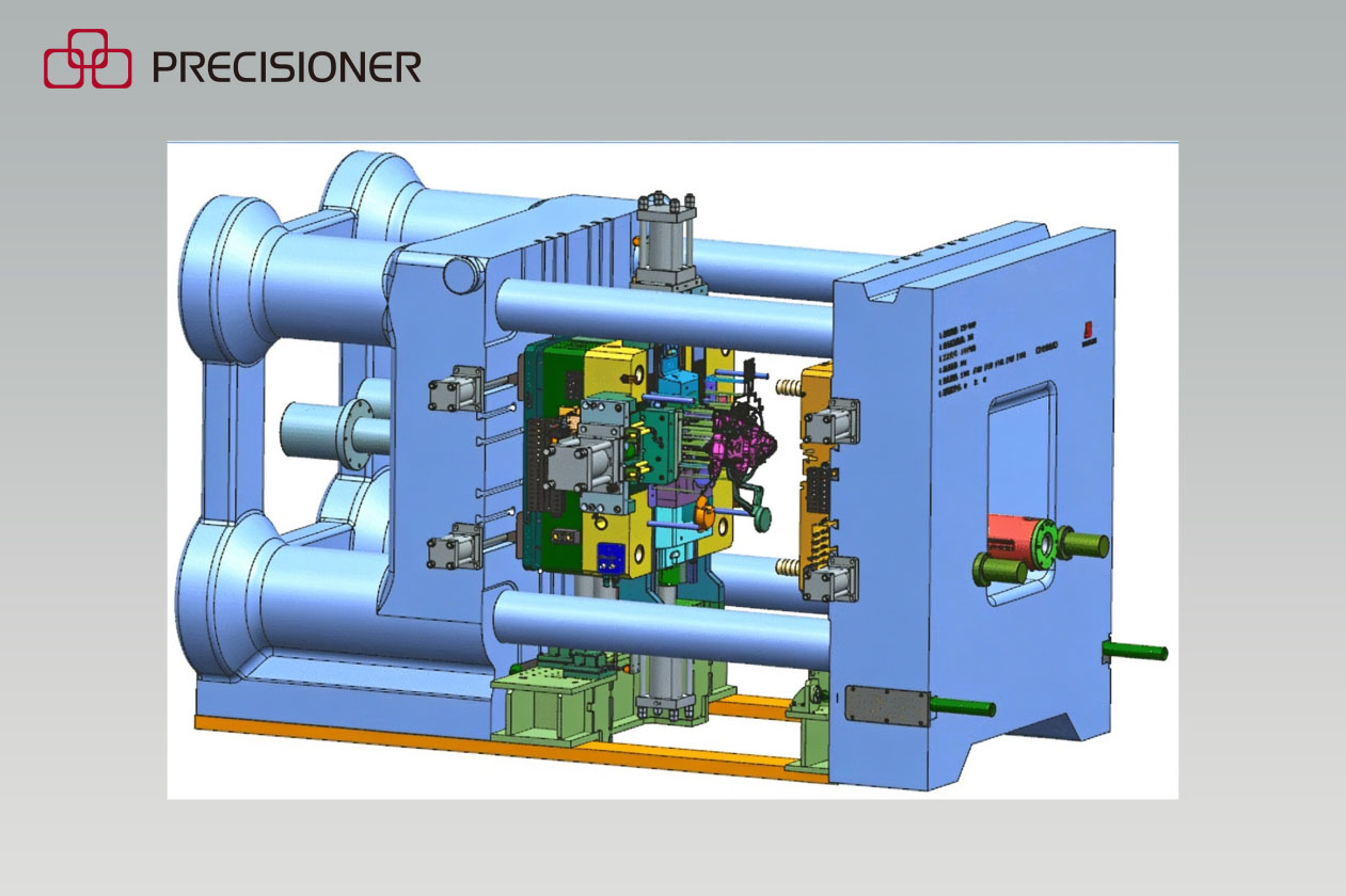
Figure 1: Press and die assembly, 3D schematic (not a photograph)
An HPDC die base is designed against two loads: heat and pressure.
Thermal load: die insert temperature typically 180–250°C, up to 300°C on thin walls, with one thermal shock per shot.
Pressure: specific injection pressure typically 40–90 MPa, with specific pressure peaks after intensification up to 120 MPa.
Dominant failure modes: plate deflection, plate cracking, guide pin seizure, and loss of fit at operating temperature.
Material and heat treatment: quenched and tempered or pre-hardened forged block, with stress relief mandatory.
Every element of an HPDC die base, from the blank to plate thickness, stress relief, fits and the guiding system, must therefore be determined from HPDC operating conditions. Experience carried over from other tooling types does not transfer.
2.1 About Forged Blocks
Blank selection is not about choosing the most expensive option but about choosing the most suitable one. Repeated forging increases the density of forgings and produces a controllable grain flow; the reduction ratio achievable in thick plates is limited, so their core soundness is often inferior. For large, critical, load-bearing mold bases, forgings should be preferred, and ultrasonic testing reports should cover the critical areas. Thermal distortion depends on the mold temperature and its distribution; uniform cooling and preheating are essential for dimensional stability.
Under cavity pressure the plates deflect, and that deflection drives both flash thickness and the accuracy retention of the die base. The actual limit depends on cavity pressure, plate span, plate thickness, support pillar layout and boundary conditions. Large die bases should be assessed individually against part tolerance and flash limits rather than adopting that range directly.
The calculation sequence is: cavity pressure, plate span, required moment of inertia, plate thickness. A classical beam model is adequate for a quick estimate on conventional support plates. For large, complex or slide-carrying die bases the simply supported approximation carries significant error, and the displacement and stress fields should be checked on a full 3D finite element model, using ANSYS, ABAQUS or an equivalent structural code. The wider the spacer block spacing, the more support pillars are required. At long spans, adding plate thickness usually costs more than adding support pillars and improves deflection less directly.
This is the step most often skipped. Rough machining introduces new residual stress. Finish machining to final size without relieving it leaves that stress locked in the plate; once the die reaches operating temperature the stress releases and the plate moves, and accuracy is lost.
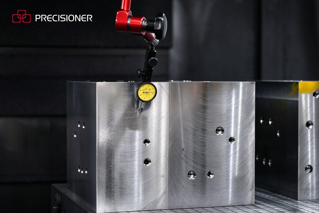
Figure 2: Die insert set up and checked for flatness.
Die bases and cavity inserts are usually made from similar tool steels with close coefficients of thermal expansion. What actually changes the fit is that their absolute growth differs: the insert has a larger section and runs hotter than the surrounding plate, so it grows more. Taking 11.5×10⁻⁶/°C as the coefficient, an 800 mm plate rising from 25°C to 200°C grows about 1.6 mm linearly, and an insert at a higher temperature grows more still.
A pocket and insert fitted to zero clearance at room temperature will therefore seize or lose position when hot. Guide pin and bushing clearance, and insert-to-pocket fits, must be specified at operating temperature rather than at the temperature shown on the drawing.
Under die casting conditions conventional grease carbonizes quickly, and dry running of guide pins is a common failure. Standard practice:
Guide pins in through-hardened SUJ2 or carburized 20CrMnTi, surface hardness HRC 58–62; graphite bronze bushings or high-temperature lubrication features; clearance opened slightly to accommodate thermal growth and fine aluminum debris; and guide pins long enough that they enter the bushings before the inserts make contact.
Four interface dimensions must come from the actual machine:
Tie bar spacing, minimum and maximum die height, clamp slot position and width, and ejection stroke with ejector rod hole pattern.
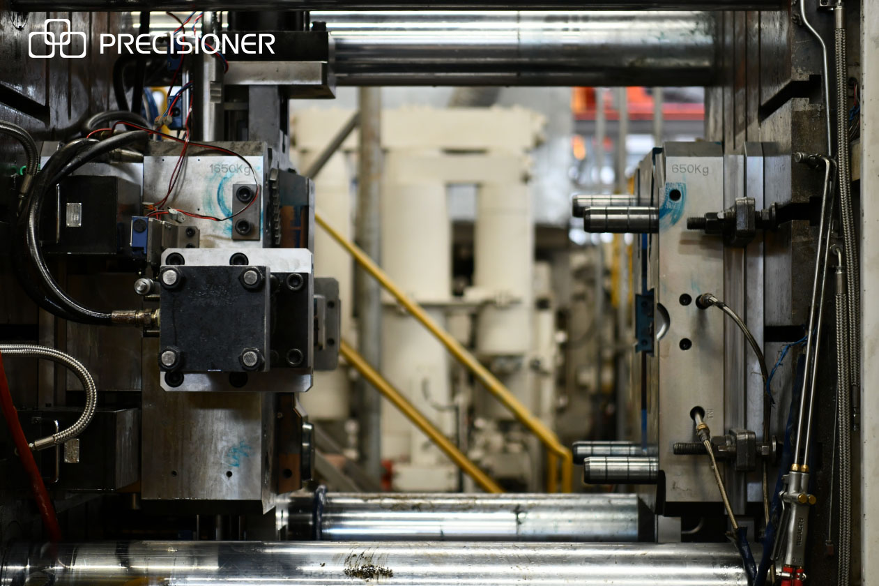
Figure 3: Die base installed on a customer press
|
Process |
Control point |
Consequence of skipping |
|
Blank and UT |
Forged block, UT report |
Internal defects propagate under pressure; plate cracks |
|
Rough machining |
Sufficient stock allowance for stress relief |
Stress cannot be released effectively |
|
Stress relief annealing |
Temperature curve, furnace cooling |
Late-stage distortion and loss of accuracy |
|
Finish machining |
Guide pin bores and insert mounting face in one setup, jig bored for position |
Bore position out of tolerance; die closes off-axis |
|
Inspection |
CMM report on parallelism, flatness and bore position |
Problems surface at the customer's plant |
Machining the guide pin bores and the insert mounting face in a single setup is the decisive step for accuracy. A second setup means re-datuming the machine, and that error transfers directly into die closing accuracy.
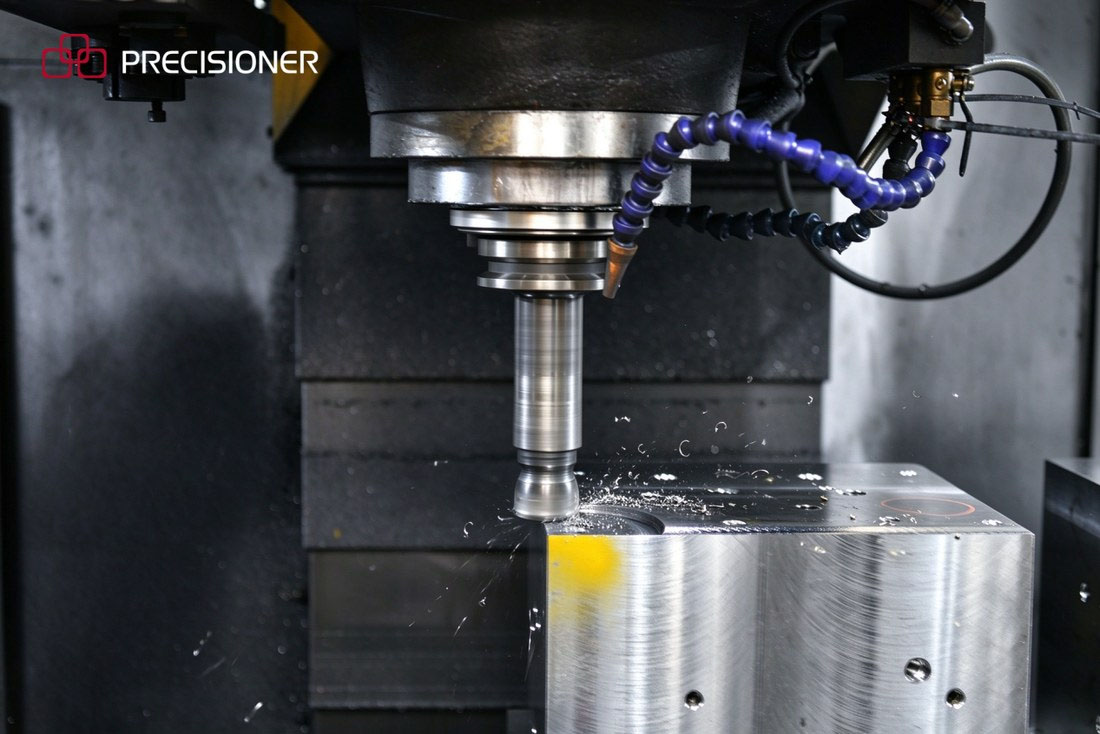
Figure 4: CNC milling of a die base plate
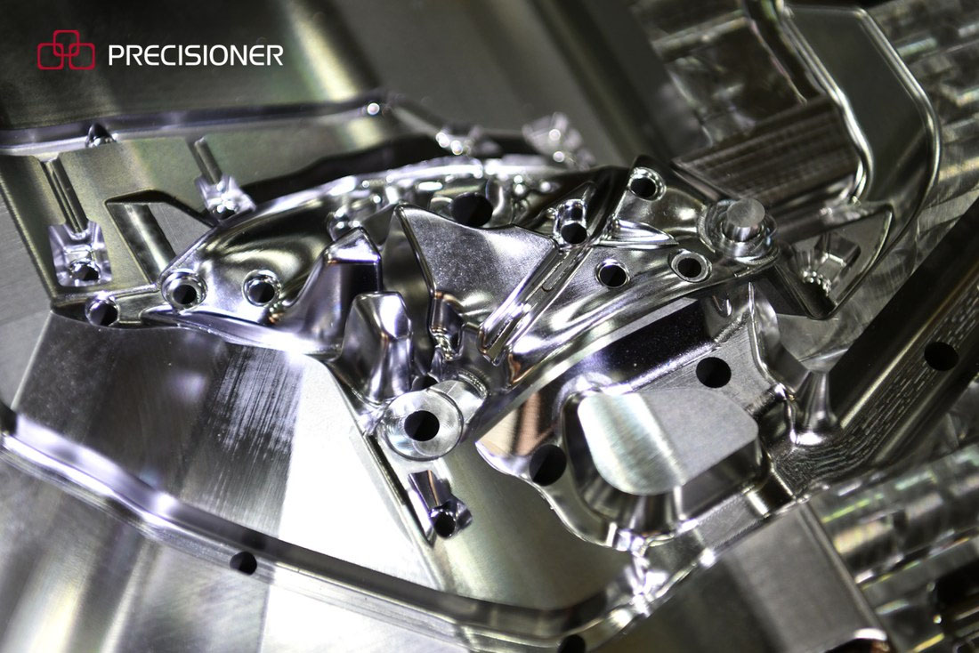
Figure 5: Cavity surface after finish machining
Laboratory material testing: the subject is the die base forging and plate
The laboratory can test die base forgings for chemical composition, mechanical properties, hardness, microstructure and internal defects by ultrasonic testing. Test standards, sampling locations, batch and report numbers should be traceable. Material testing addresses the die base material itself and does not replace verification of the insert material and its heat treatment.
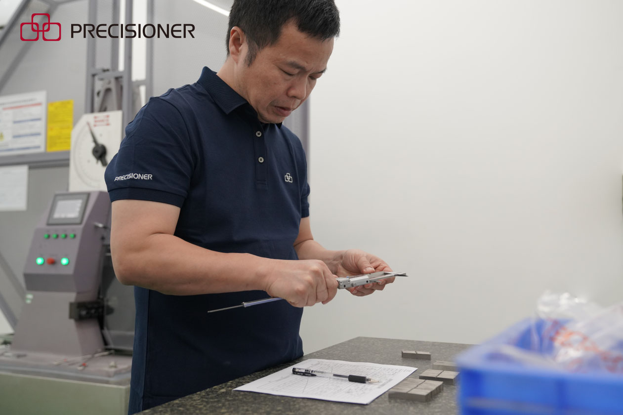
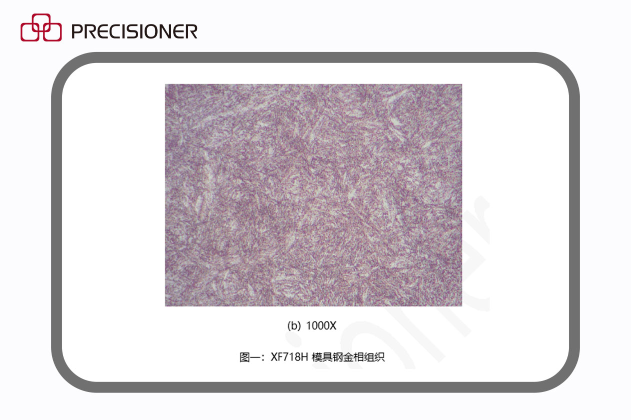
Figure 7: XF718H die steel microstructure (1000×)
Method. Die bases are built to the customer's machine dimensions. Blanks are forged and ultrasonically tested. The die base material goes through laboratory testing. Stress relief annealing is performed after rough machining and again after semi-finishing. Guide pin bores and the insert mounting face are jig bored in a single setup. Guide pin and bushing fits are machined to clearance at operating temperature. MAGMASOFT is used for thermal balance simulation, and thermography is used during die trial to verify the temperature distribution.
• Forging material certificate and forging UT report;
• Die base material laboratory report covering chemical composition, mechanical properties, hardness and microstructure;
• die trial thermography temperature record;
• Die base to machine interface ///confirm/i/i/iation sheet;
Benefit. With interface dimensions ///confirm/i/i/ied, the die goes onto the press without on-site fitting of clamp slots. Plate deflection stays within the calculated range, so flash is controlled more consistently. Guide pins neither seize nor bind, which reduces unplanned downtime. Thermal balance has both a simulated and a measured basis, so hot-state fits are more predictable. These benefits come from the die base's resistance to deflection, its guiding and its interface fit; they do not replace insert material selection or thermal cycle management.
None of the six requires opening the die; the reports and process records are enough.
• Is the blank forged or cut from plate, and is there a UT report?
• Does the die base material have a report covering chemical composition, mechanical properties, hardness and microstructure?
• How many stress relief cycles were performed, and are the temperature records available?
• Were the guide pin bores and the insert mounting face machined in one setup?
• What are the measured parallelism, flatness and bore position values, and against which standard were they judged?
• Is there a thermal balance simulation report and a die trial thermography record, and do the results fall within the criterion?
An HPDC die base does not determine how good a first part the insert can produce, and it does not replace insert material selection or thermal cycle management. It determines the accuracy retention of the die base itself, and through that whether the die still holds the same accuracy in year three to year five. None of the six requirements can be replaced by experience, stress relief and interface dimensions least of all. Material testing, thermal balance simulation and thermography are the means of closing the gap between hot-state dimensions and thermal balance assumptions and the real die; they do not cover the structural calculation of plate deflection and thickness, and they cannot replace plate thickness calculation, single-setup machining or CMM inspection. What appears to be saved is repaid at the customer's plant, at a higher price.
Working on a new die base or a replacement? Send us the part drawing and the press model, and we will return a die base structure proposal, the basis for the plate thickness calculation, and an interface ///confirm/i/i/iation sheet.
Precisioner | High-Pressure Die Casting Dies and Process Validation
info@precisioner.com | www.precisioner.com