

The engineering complexity of large-scale die casting molds is far from a simple proportional scale-up of smaller dies. As die dimensions expand from 300 mm to over 1,000 mm, multi-physics coupling effects emerge at scale that simply do not exist in smaller dies — leading to issues such as uneven filling, slider seizure, and out-of-tolerance dimensions. If you are advancing a large-scale integrated die casting project, this article shares practical engineering insights accumulated from production-validated experience across the full range of 300T to 4,500T machines.
The engineering complexity of large-scale die casting molds is far from a simple proportional scale-up of smaller dies. As die dimensions expand from 300 mm to over 1,000 mm, multi-physics coupling effects emerge that simply do not exist in smaller tools — leading to uneven filling, slider seizure, and out-of-tolerance dimensions. If you are advancing a large-scale integrated die casting project, this article shares practical engineering insights accumulated from production-validated experience across the full range of 300T to 4,500T machines.
What Changes When You Scale Up
1. Thermal Expansion Becomes the Primary Concern
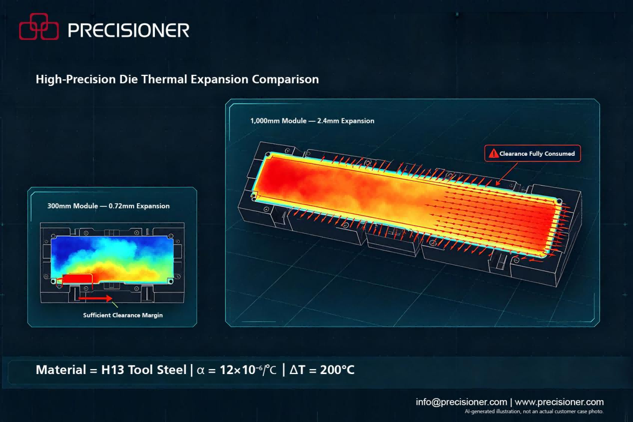
Using H13 tool steel (linear CTE ≈ 12×10⁻⁶/°C) as a uniform temperature-rise case study: a 300 mm guide width undergoing a 200 °C uniform temperature increase expands by approximately 0.72 mm; at 1,000 mm, the same uniform temperature rise produces 2.4 mm of expansion. If the cold-state assembly clearance is only 0.3 mm, the clearance is theoretically consumed entirely upon heating — resulting in seizure.
Note: The 2.4 mm figure above is a theoretical calculation based on uniform temperature rise; in production dies, a uniform 200 °C across the entire die does not exist — significant temperature differentials occur between zones.
In actual production, 200 °C represents a typical measured temperature in select zones under steady-state conditions — the die does not heat uniformly. When sliders in large dies experience high-temperature seizure, the primary cause is typically non-uniform thermal expansion compressing assembly clearances, which then compounds with lubrication breakdown and wear — it is not simply a lubrication failure. Thermal deformation is governed by local geometry, cooling channel layout, and cycle time, with significant variation across different zones. Therefore, die clearance compensation cannot rely on a single global expansion coefficient. The correct approach is: first identify the actual temperature differential across different die zones, then calculate zone-specific compensation values, and ultimately develop a zoned compensation strategy.
2. Filling Behavior Changes Fundamentally
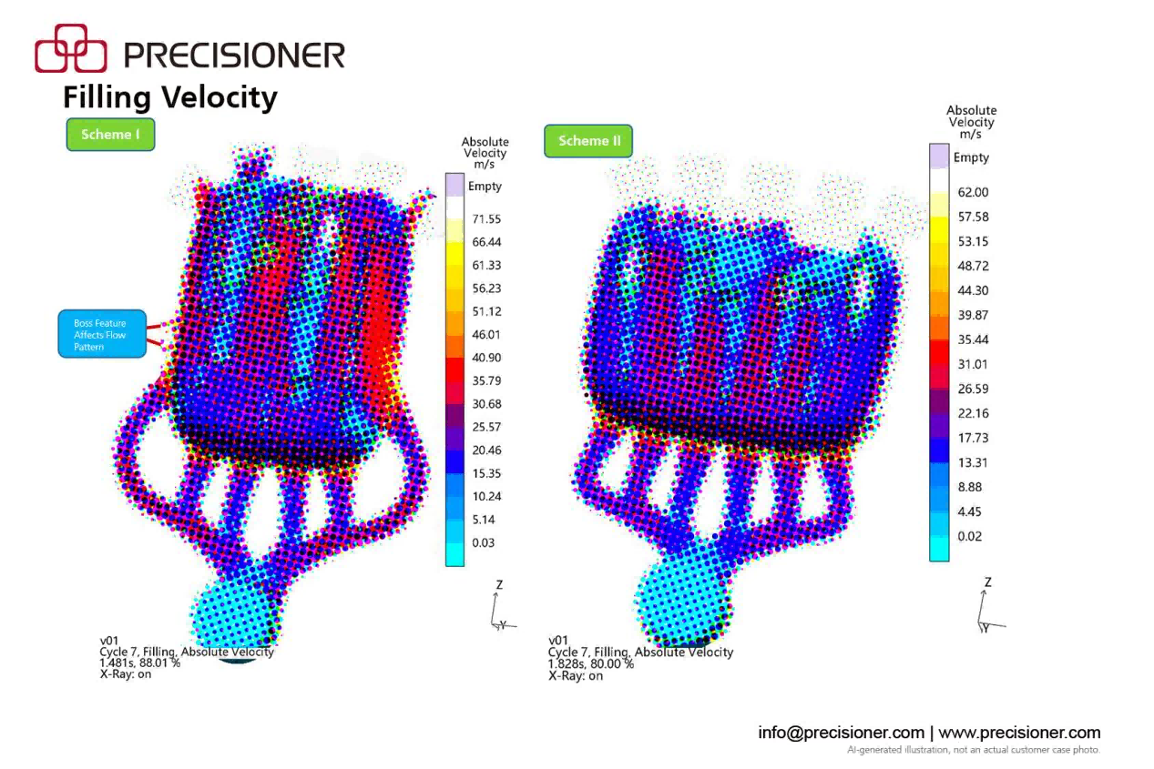
Large integrated die casting cavities have longer flow paths and greater cavity spread. As the molten metal travels to the far ends of the cavity, significant temperature drop occurs. For 500T-class die castings, flow paths typically fall within the 80–120 mm range; for 4,500T-class large parts, flow paths commonly exceed 400 mm, with certain complex local areas reaching over 600 mm — the temperature difference between the gate region and the far end of the casting can reach 30–50°C.
Longer flow paths trigger a chain of effects: progressive melt temperature drop reduces fluidity at the far end, pressure loss increases along the flow path, venting paths lengthen accordingly, and air entrapment risk rises significantly. Gate designs, shot profiles, and venting schemes proven on smaller dies often fail when directly transferred to large HPDC molds. The underlying physics have not changed — rather, the generous process margins available at small scale transform into tight critical constraints at large scale.
3. Die Deflection Can No Longer Be Ignored
Under 4,500T clamping force, the platens undergo measurable elastic deformation, altering the cavity geometry during filling and solidification — which in turn affects casting dimensional accuracy, parting line flash, and internal porosity distribution. This deformation is repeatable elastic deflection that must be compensated for during the die casting mold design phase through pre-distortion, counteracting the cavity distortion caused by clamping force — rather than reactively addressing it during trial.
At the same time, large dies are difficult to fill, often requiring plunger tip speeds of 7 m/s or higher. The melt impact forces and die erosion effects from high-speed filling must also be factored into gating system design and die heat treatment specifications.
For large integrated die casting molds, designs that lack simulation-based pre-compensation and rely solely on traditional empirical hand calculations face extremely low odds of achieving stable mass production.
4. Trial-and-Error Costs Escalate by Orders of Magnitude
The cost of a large die extends far beyond material — it encompasses long-cycle machining, assembly, commissioning, and validation. Each die trial consumes not only aluminum alloy raw material and machine hours, but also scarce engineering resources. Even more significant is the commercial cost of time: for vehicle programs with annual volumes exceeding 100,000 units, industry experience suggests that each week of delay at key project milestones (TTO/OTS sample delivery) can result in losses reaching millions of RMB. A single failed die trial on a 4,500T machine carries financial and schedule consequences that are entirely incomparable to those on an 800T machine.
First-trial success rate on large integrated die casting projects is therefore not merely an engineering optimization metric — it is a hard commercial and timeline constraint.
Field-Validated: These Principles Work
The following principles come from our project practice across 300T–4,500T dies and have been validated through mass production programs.
Compensation Must Be Zone-Specific
Relying on uniform thermal expansion compensation cannot meet the demands of large dies. Different zones of a large die experience vastly different thermal loads — the thermal deformation behavior at the cavity center versus slider areas differs dramatically. Our engineering workflow: calculate zone-specific compensation values → validate via simulation → conduct controlled trial for fine-tuning. In a 4,500T-class rear floor die project, with cooling, injection process, and cycle time held essentially consistent, the zoned compensation approach reduced casting dimensional deviation from ±1.2 mm to within ±0.3 mm.
Trial Strategy Matters More at High Tonnage
Small-tonnage dies can absorb multiple iterative trials; at high tonnage, every trial round is costly. Recommended workflow: thorough upfront simulation → develop a targeted trial plan → prioritize validation of high-risk areas → verify simulation predictions through structured measurement (3D scanning, CT, cross-sectioning) → lock in mass production process parameters. For newly developed large structural parts of moderate complexity, this workflow has reduced trial counts from the industry-typical 5–8 rounds down to 2–3, significantly reducing commissioning cycles and total cost.
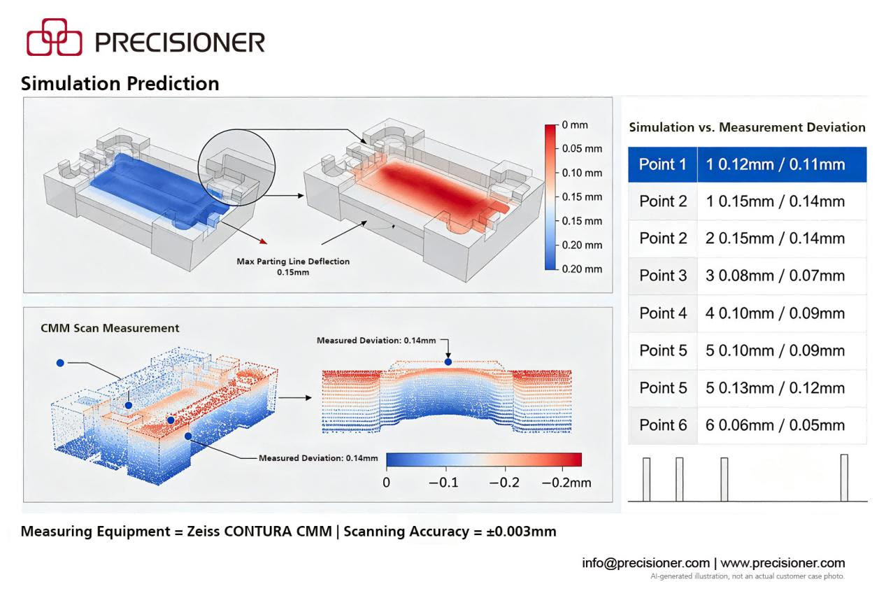
Directly copying process parameters validated on another project does not constitute process validation for the current project. Die casting process parameters are highly context-dependent, influenced by die condition, machine, aluminum alloy batch, and cycle time in combination. Effective validation requires understanding the underlying logic behind the parameters: how thermal balance is established, whether filling sequence is sound, whether venting design is adequate — /confirm/iing that the specific die-material-machine combination on this project can stably produce conforming castings.
Emerging Trends
The industry is accelerating its shift toward integrated development models. The core capability can no longer rest on a unidirectional linear flow of "Design → Simulation → trial." It must evolve into a closed-loop iterative chain: Design → Simulation → Physical Validation → Data Feedback → Calibrated Simulation Boundaries.
In this closed loop, every trial's 3D scanning data, thermal imaging curves, machine pressure signals, and defect inspection results are fully digitized and fed back into the simulation model, continuously refining simulation boundary conditions so the model progressively converges toward actual physical conditions. Companies excelling in large-scale integrated die casting are not necessarily those with the most expensive simulation software or the highest-tonnage machines — they are the ones who first established this closed loop, continuously accumulated engineering data, and made each successive simulation iteration incrementally closer to physical reality.
Precisioner offers full-process capabilities from die casting mold design and die casting mold manufacturing through trial validation, with die compatibility ranging from 60T to 6,600T, supported by a CNAS-accredited steel laboratory and a structured process validation system.
Closing
If you are evaluating or developing large-scale integrated die casting components, we welcome you to schedule a technical discussion — we can engage in an in-depth review of your trial strategy and validation path based on your specific part requirements.
info@precisioner.com | www.precisioner.com